
Water jet propulsion and control systems. Designed, machined, assembled and tested in‑house.
Axial flow jet drives up to 300 HP / 224 kW and CAN-based control electronics for shipyard OEM programmes, rescue and military craft, and unmanned surface vessels.
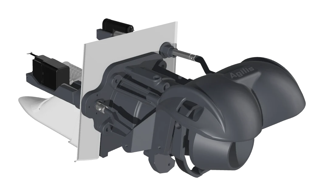
Jet drives: standard lead time 4 weeks, confirmed on order, 12-month warranty.
The platform
One platform: the drive and its controls
Propulsion hardware and control electronics developed under one roof, with integration tailored to each vessel.
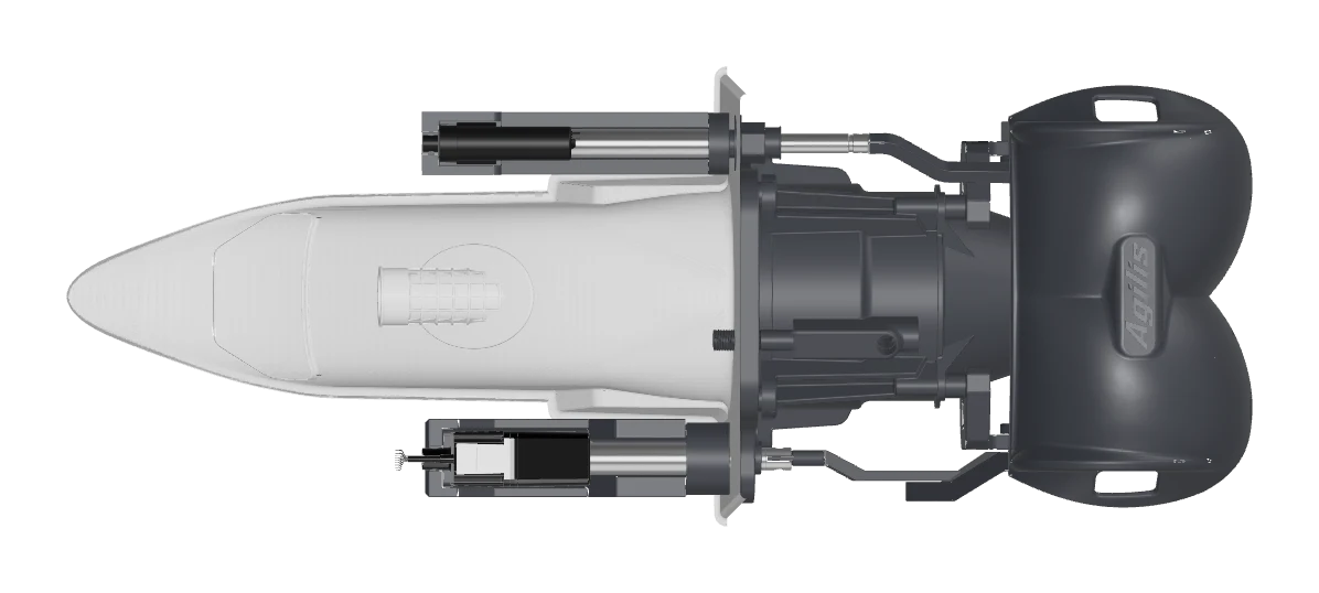
Axial flow water jets
Agilis Water Jet 186 (AWJ 186) and Agilis Water Jet 200 (AWJ 200): up to 300 HP / 224 kW, up to 50 kn, from 29 kg. Die-cast aluminium construction, electric reverse as standard, optional ±10° trim nozzle. A third model is in development.
View the range →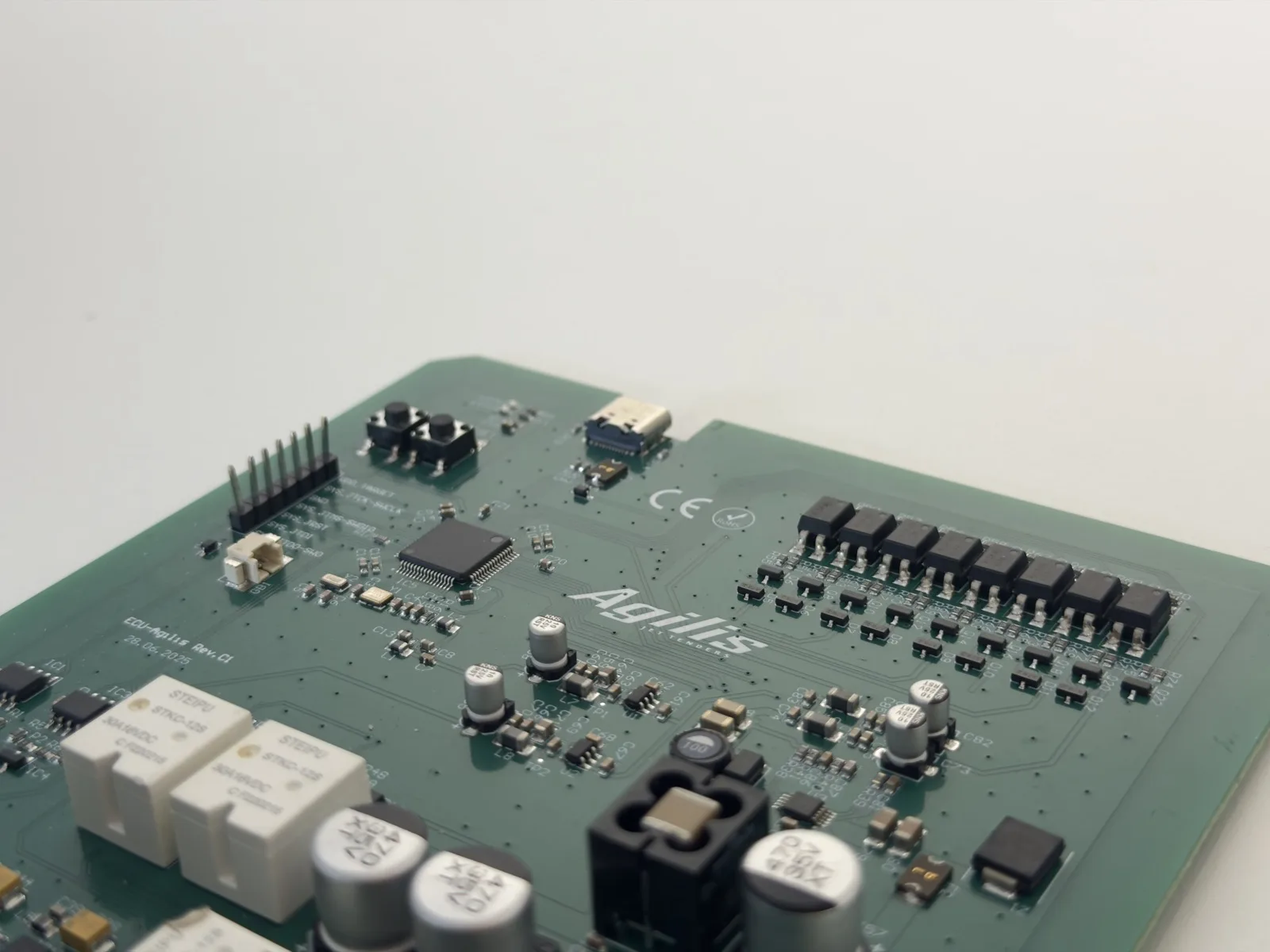
Agilis Vessel Control System
The Agilis Vessel Control System is two modules designed in-house, the Agilis ECU and the Agilis Multi-CAN Gateway, that work on their own or together on a shared CAN network. The Agilis ECU turns commands from a CAN throttle/shift lever into analog throttle and shift signals, and the Gateway publishes engine data, two tank levels and digital switching on NMEA 2000 for a compatible multifunction display (MFD). Electric steering and autopilot are available separately.
Explore electronics →From the helm to the drive, and engine data back to the display
- Shared CAN network
- CAN connection
- Analog signal
- Single reversible power output
- Configuration access
- Agilis module
Connections in the example system:
- The CAN throttle/shift lever sends its commands over the shared CAN network (engine and control).
- The Agilis ECU is connected to the shared CAN network and receives the lever commands there.
- CAN actuators receive their commands over the shared CAN network.
- The engine, one or two, puts its engine data on the shared CAN network over CAN J1939 or CANopen.
- The Agilis Multi-CAN Gateway is connected to the shared CAN network on its channel CAN 1.
- The Agilis ECU sends analog signals from its DAC channels to the engine, one or two (long dashed line).
- The Agilis ECU drives the reverse actuator through its single reversible power output (double line).
- A CAN keypad and the Gateway exchange button commands and switching status on channel CAN 2.
- The Gateway sends data to the multifunction display (MFD) on channel CAN 3, the NMEA 2000 network.
- Two tank level sensors send analog signals to the Gateway (long dashed line).
- The Agilis CAN adapter connects to the shared CAN network for configuration and updates (dashed line).
Applications
Configured for your duty cycle
Shipyard & OEM integration
Drives engineered for series production, with the integration support to put them in your hull.
Recommended: AWJ 186 or AWJ 200, GRP wedge, electric trim nozzle, Agilis ECU for throttle and reverse control, Agilis Multi-CAN Gateway for engine data on NMEA 2000.
See OEM integration →Rescue & military craft
Shallow water, debris and hard duty cycles: propulsion for boats that cannot afford downtime.
Recommended: AWJ 200 (single or dual), electric trim nozzle, Agilis ECU for throttle and reverse control, Agilis Multi-CAN Gateway for engine data on NMEA 2000 and digital switching of less critical circuits.
See rescue & military →USV & autonomous platforms
The drive plus CAN-commanded throttle and reverse control, and engine data on NMEA 2000.
Recommended: AWJ 186 or AWJ 200, USV controls preparation, Agilis ECU for throttle and reverse control, Agilis Multi-CAN Gateway for engine data on NMEA 2000.
See USV integration →Why Agilis Jet Technologies
Built by the people who install them
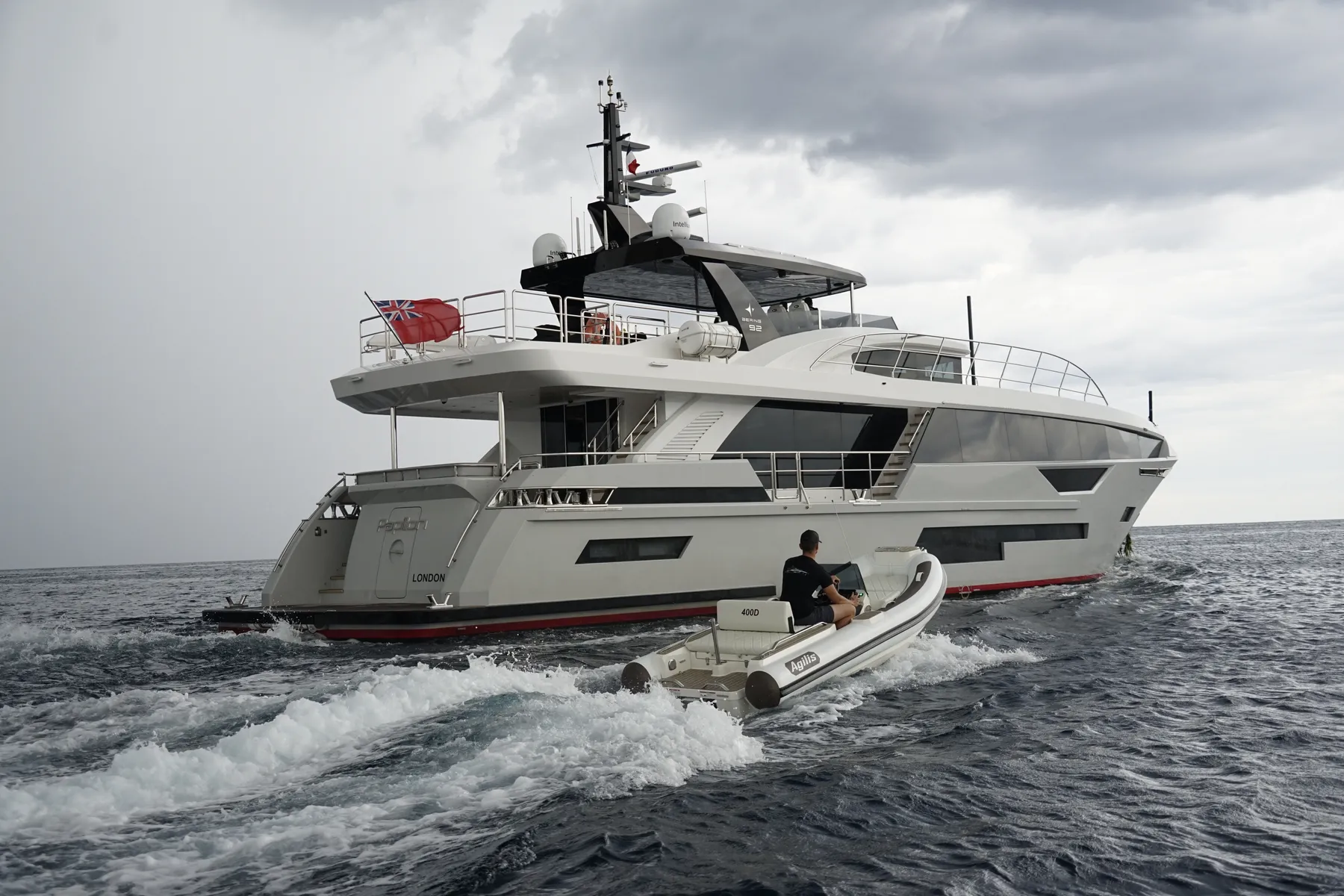
Agilis Jet Technologies shares its owners with Agilis Jet Tenders. The drives run in Agilis boats today, and the integration experience is older than the product.
We do not sell a drive we have not put in our own boat
Agilis drives run in Agilis tenders today. A supplier who ships pumps to yards lives with none of the consequences; we ride on ours.
Revised before released
The design went through multiple revisions before we released it.
Integration experience predates the product
Years of installing jet drives into the Agilis 360D and 400D came first. That is what designing from the boat backwards means: the drive is shaped by the installation, not the bench.
A method you can interrogate
Sizing runs on the Savitsky method and our parametric pump model, validated against a CFD target and published with tolerances. Read how the engineering works.
Talk to our engineers
Tell us about your platform. We answer with data, drawings and a configuration that fits.